Thomas Salt, Museum Technician
Frances Hartog, Senior Textile Conservator
The Victoria and Albert Museum’s exhibition ‘Opus Anglicanum: Masterpieces of English Medieval Embroidery’, held from 1 October 2016 to 5 February 2017, is the first time in two generations that so many of these exquisite embroideries have been brought together for display. To ensure the safety of the magnificent but fragile copes and chasubles during the exhibition, including loans from the Museo Arquéológico Nacional, Madrid and the Metropolitan Museum, New York, a total of nine bespoke three-dimensional mounts were required.
Previous experience from the redisplay of the Medieval & Renaissance Galleries (M&R) proved that displaying medieval vestments on individually shaped, properly fitting three-dimensional mounts minimises the necessity for interventive conservation. For objects that have survived for over 600 years and undergone generations of repair, this is an invaluable asset. The three-dimensional mounts that were commissioned for the M&R galleries were produced by an outside supplier specialising in sheet metal work. Though well executed and beautifully finished, having tailored mounts made off site was difficult and time consuming. It was also costly, which though acceptable for permanent galleries, could not be afforded for a short term display.
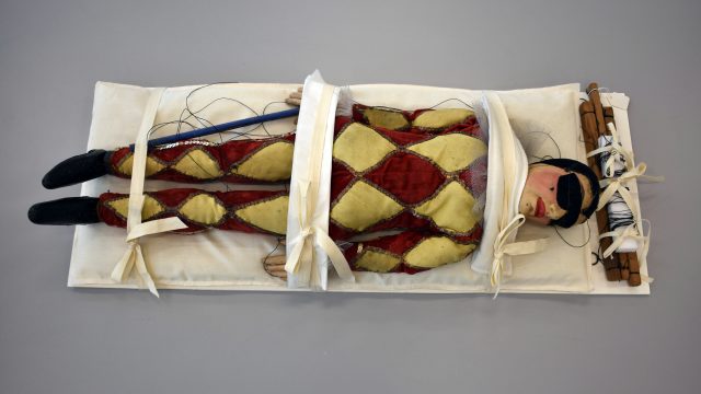
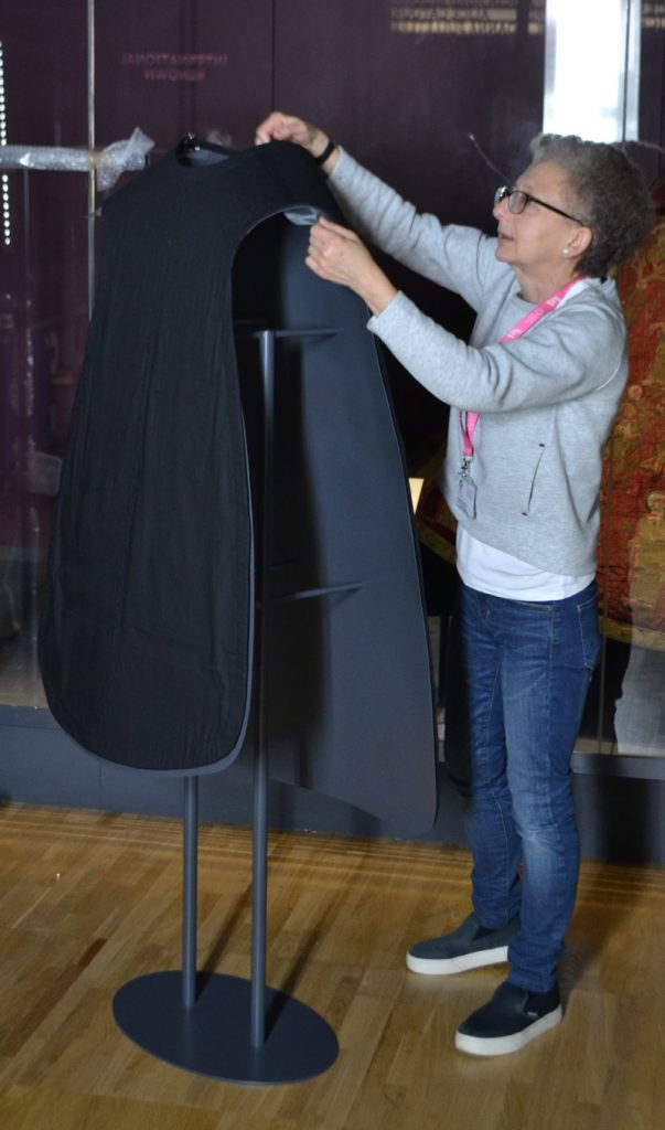
When commissioning mounts for Opus Anglicanum, Conservation’s brief for the Technical Services Team was to produce mounts individually fitted to the nine vestments. They should be unobtrusive, lightweight but stable whilst providing maximum support. Conservation would provide calico toiles (exact copies of the garment) for each object. The toiles could then be used by Technical Services to fashion the customised shapes, avoiding the necessity of handling and trying-on the original vestment. Conservation would also produce thin, padded covers for the mounts. The cotton-covered pads would be attached to the mounts using Velcro. The fixed, non-slip pads and the shape of the mounts would negate the need for the objects to be secured, they would simply lay over the mounts.
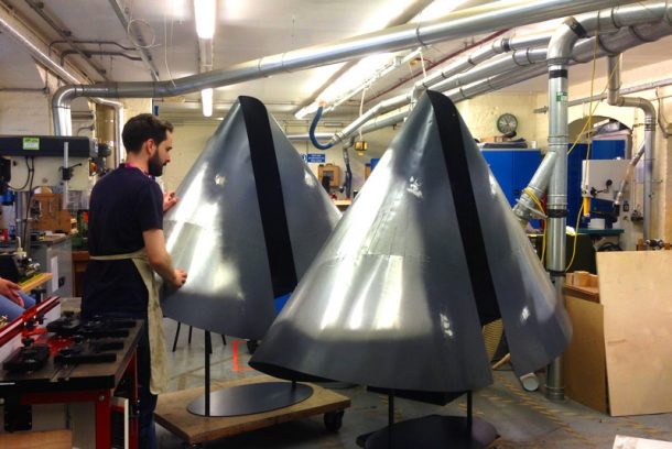
Technical Services decided early on to separate production of the mounts into two halves: the fabrication of ridged, hollow shells to support the vestments for display, and the fabrication of stands onto which the shells would sit. The units would then be fitted together to create the final mount. This decision enabled the team to focus on the element of most concern for Conservation, the fit of the shell, and to outsource the more generic stand construction.
To attain the correct shapes, any solution would need to rely on translating the flat geometry of the toiles into bespoke three dimensional support shells. This could only be achieved by deconstructing the toiles back to garment parts, from which accurate pattern templates could be made. These component shapes could then be transferred onto sheet material, cut, bent and joined – in much the same way as pattern pieces are cut from fabric and sewn together in the making of a garment. This approach had the great advantage of fidelity to the original throughout the making process; if the assembled pattern replicated the vestment in the form of a calico toile, it stood to reason that the same theory applied to the construction of the support shells.
The decision to work from flat patterns meant that a sheet material capable of being bent in multiple directions, neatly joined, and possessing the necessary rigidity, needed to be found. While sheet metal was the obvious choice from the outset, we resisted exploring this option because of a lack of sheet metal working experience within the team and the assumption that mechanical rolling equipment, panel beating experience, and tungsten inert gas welding would be required. To mitigate these reservations, an initial attempt was made to reduce the complex curves to a faceted geometric model, folded from a net of the solid. The two-dimensional pattern was cut in aluminium composite sheet (Dibond) and bent along a series of V grooves routed in the surface. This proved unsuccessful because the aluminium composite became brittle through stress and fractured along the bends. This experiment was invaluable however, because while ultimately proving unsuitable, it required the marking out of radial lines approximating the direction and intensity of the final curves across the pattern pieces, and the joining of the bent components using cold rivets (Figure 1). These techniques simplified and directed the bending process and removed the need for skilled welding operations.
More serious thought was now given to the use of sheet metal products; initially considering thin gauge, perforated aluminium sheet or mesh because of its apparent bending and stretching properties; and then solid aluminium sheet of different gauges, eventually selecting a 1.5mm sheet. In tests this thickness proved to combine the right balance between ease of working and rigidity, being lightweight and strong once the desired bends had been achieved.
Positioning joins in the patterns presented the next challenge; this required deviation from the textile patterns because it was apparent that seams running across the shoulders would weaken the chasuble support shells and exacerbate problems with achieving satisfactory bends in these problematic areas. Instead, seams were placed transversely on the chest and up the line of the sternum. Cold riveting was used to secure the joins, made with a shaped joining plate also cut from aluminium sheet. In these positions the additional material increased the strength of the shell and knitted the components together; importantly the joins were also discreet in the final mounts. Seams were placed in the cope support shells with the same consideration: to achieve maximum strength without disrupting or weakening the curve.
Each support shell was made in the following sequence. After receiving a toile from Textile Conservation, paper templates were made of the pattern pieces, with adaptation to reflect the altered join configuration. A network of radial lines representing the curvatures in the finished shell were drawn on the paper and then this information was transferred onto the sheet aluminium. The individual components and joining plates were cut out using a Jigsaw and a rail guided circular saw, mounted with aluminium cutting blades. The edges of the shapes were then finished using hand files. The components were cold bent by hand (according to the regularity and direction of the prescribed line configurations) over, or clamped underneath, wide diameter steel tubing and then joined at the seams using the cold rivets. Once assembled, further cold bending and adjustment was carried out using steel tubes as jigs, and a small panel-beating kit containing a selection of hammers and dollies; however this proved necessary only on the neck line and in the transition between the shoulders and chest, removing the need for a significant level of metal working experience. The finished support shell was attached to a temporary stand and delivered to Conservation for the fitting of the toile, and further adjustments suggested if required.
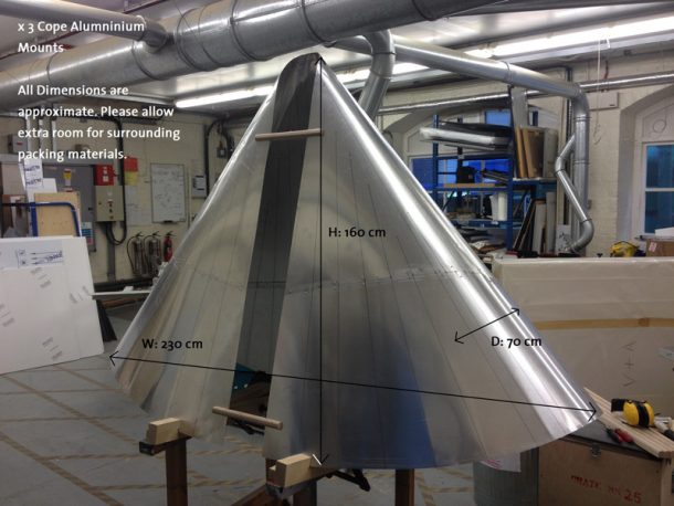
One problem encountered was the lead time for outside metal fabrication, which required an order to be placed for the stands before all of the support shells had been made, and therefore before detailed measurements could be taken. This was overcome by designing three basic stand configurations covering predicted variations in the size and shape of the shells, and by oversizing supporting members to be cut and ground down to marry up later in-house. Technical drawings were produced in CAD to clearly communicate requirements to the external contractor and provide lenders to the exhibition with a schema for their approval. Due to their size once completed, the support shells were sent out to be sprayed (with a two pack polyurethane paint with cellulose base) and returned along with the powder coated stands. The two elements were then fitted up and finally attached together using machine screws (Figure 2).
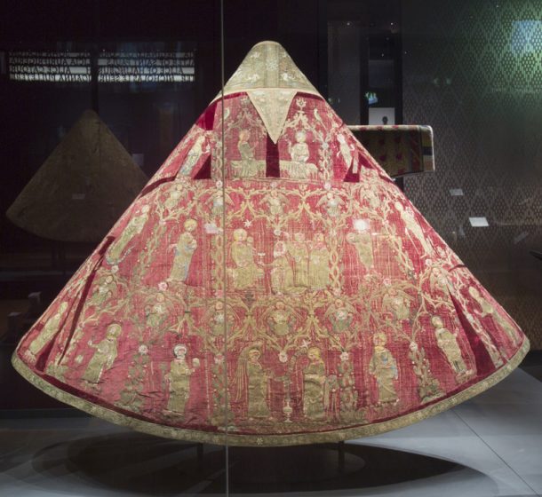
Technically the success of this method came from its relatively simple logic, breaking the work down into repeatable steps, and by imaginatively employing the equipment and skills available. A good fit was consistently achieved with the objects; this was the fruit of time spent in advance developing a workable system, without which the present solution could not have been reached. The final appeal of any mount is in part due to the application of abstract aesthetic ideas; what makes a mount look ‘right’, or one object appear to sit ‘comfortably’ and another not, is a matter of personal sensibility. However, one advantage that mounts commissioned in-house have over a more commercial solution is that a dedicated workshop develops a culture of sensitivity towards the visual aspects of mount design alongside the technical skills necessary to realise them. The chasuble and cope mounts made for Opus Anglicanum satisfied the conservation brief and the design aesthetic, enabling these fragile medieval vestments to be displayed safely and beautifully (Figures 3 and 4). As one lender attested of their mounted object, “That’s amazing, I have never seen it look so good”.
Support generously provided by The Ruddock Foundation for the Arts.
Supported by Hand and Lock.
Runs until 5th February 2017.