Conservation Journal
April 1992 Issue 03
The Mounting and Framing of a Large Work of Art on Paper; a Case Study
The subject of this case study is a print (aquatint, soft ground etching and 'chine colle') titled 'Semen' by Francesco Clemente (Museum no. E.1214-1989). It was printed in 1987 after a 1983 painting by the artist. It measured 77.8 x 235.0 cm and had been stored rolled, wrapped in paper, in a cardboard cylinder.
There are many problems encountered when mounting and framing large scale works of art on paper. These involve both questions of storage - should the object be rolled up, framed or stored flat? - and of display - what type of frame should be used, should there be a mount, should there be glazing?
Curatorial decisions were made that the print would be mounted and framed and that a border was to be shown around the image. These decisions were reached because the object was required for the Post-Modern printmaking exhibition in the summer of 1991, and due to its size, it would ultimately be stored at Blythe Road. Consequently the more protection it received the better.

Fig 1. Cross section of frame and mount (Computer Aided Design by Ian Shaw from art work supplied by Nicki Edwards Smith) (click image for larger version)
Before the moulding for the frame could be chosen a few points had to be considered. Due to its size, the profile of the frame would have to be quite broad or it would bow outwards from the weight of the mounted object. The surface of the print was quite vulnerable and had additions of a non-paint medium (metallic foil and string). Therefore, in order to protect this surface, the frame would need glazing. It would be unrealistic to use plate glass, mainly because of how heavy such a size sheet would be. The other option was Perspex which would weigh less and would be more desirable from a safety angle. The decision to use Perspex as glazing then made the need for a mount more apparent as an expanse of Perspex this size, even at 6 mm thick would have considerable whip. Therefore, in order to keep the glazing away from the surface of the object, the degree of flex (plus approximately 5 mm air space to allow for static pull between the object and the glazing) had to be calculated. These measurements gave us the depth of the window mount; to this we added the thickness of the Perspex, the mount back-board, the frame backboard and approximately 10 mm to give an air gap between the frame backboard and the frame moulding. This gap is to prevent the back of the framed object being totally flush with the display or storage wall, which would prevent the free flow of air around the object and could result in a build up of moisture behind the frame. These combined measurements gave us the depth of the frame rebate (Fig 1).
The overall size of the mount and frame was to be larger than the object to allow for the hinging to the backboard. Having finalised the dimensions, the profile and colour of the frame moulding were chosen by a member of the curatorial staff and the Joiners were able to proceed with the construction of the frame.
While we waited for the frame to be completed we began to design the window mount, which we calculated to have a required depth of 15mm. The selection of materials was determined by four factors:
1 Cost
2 Availability
3 Archival quality
4 Weight
The mount board we use as standard in our section is Atlantis 2200 µm cream museum board. However, the largest size manufactured fell far short of the size of the mount. Laminating sheets of the board would be time consuming, costly and would take at least five layers of board which would weigh a considerable amount, so alternative types of board had to be sought. Primarily we looked at a honeycomb core board called Tycore which is manufactured in the USA. Its sheet size and thickness were ideal, it was of archival quality and due to its honeycombed structure was lightweight. However, on construction of a corner sample, we found it was quite difficult to achieve a bevelled edge of a satisfactory standard; also its surface was not totally smooth and would need facing with at least two layers of paper. The use of Tycore was finally ruled out when we discovered that what stock was in the Museum was to be used for mounting objects for the Tsui Gallery and that no more was available for import for at least six months.
On further consultation with our board suppliers, Atlantis Paper Company, we eventually opted for their Archivart multi-use board. This is a blue board with a corrugated core which has a layer of card on each side. It is available in single and double wall sheets which were large enough to span the length of the frame. We decided to use the single wall sheets, as this gave us more control over the mount thickness and methods of jointing the corners.
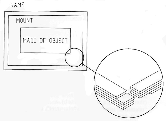
Fig 2. Construction of corner joints (Computer Aided Design by Ian Shaw from art work supplied by Nicki Edwards Smith) (click image for larger version)
We began making the mount by cutting the board to size in strips and gluing them together with Tenaxatex ws 3978 PVAC adhesive and drying the pieces under weights. By layering the board to achieve a mortice and tenon style joint (Fig 2), we were able to construct a stronger corner joint. When dry the corners were glued up and slotted together, one horizontal and one vertical, weighted and left to dry. The two 'L' shaped pieces were joined in the same manner to achieve a rectangular mount. When dry, we were ready to cut the bevelled inner edge. An attempt was made to cut this with an electric jigsaw with a 45° attachment, but this damaged the board too much. We reverted to cutting by hand using a scalpel.
Originally we had planned to face the multi-use board with a heavy cartridge paper of a colour similar to that of the object, but found that the board surface was far more uneven than we had judged, and that on applying a test layer the appearance was unsatisfactory on both the face and bevel, which would be exaggerated by overhead exhibition lighting. Our second option was to face the surface with 2200 µm museum board. This not only overcame the problems of unevenness but also allowed us to make the bevelled edge look far sharper. The facing boards were applied in as large sections as possible to reduce the number of joins. The bevelled edge was faced with strips of board cut with an angled edge to create a join flush with the facing board. When dry, any gaps were filled with rolled Japanese paper to reduce any unevenness.
Problems were experienced when the facing paper was applied. We had found a suitable paper in roll form which allowed us to cover each side in one piece, but corners had to be mitred and bevels covered and wrapped. It was quite difficult to cut the correct angle when wrapping the bevel at the corners, resulting in gaps where the paper joined. Therefore templates were cut in silicone release paper to increase accuracy. This problem was complicated as the paper stretched quite badly when in contact with moisture from the adhesive, but we found that by cutting the mitred joints oversize and trimming them up before the adhesive set off that this problem could be overcome. Despite the paper stretching we managed to cover all the sides successfully apart from the last one which cockled badly. We attempted to flatten it by applying a heated spatula and by injecting adhesive into non-adhered areas with a syringe; but without success, resulting in the paper being stripped off and residual adhesive sanded down. The second attempt was satisfactory. On completion of the window mount the object was hinged to its backboard which was made from four outsize sheets of Atlantis 2200 gm museum board butted together, two horizontally and two vertically and glued with Tenaxatex PVAC to form a double thickness board. The print was hinged all round with wheat starch paste and Japanese paper hinges 20 mm wide and 40 mm long. These were then 'T' hinged to the mount backboard. The frame backboard was made from two sheets of 3 mm hardboard butted together and joined with a strip of linen and Tenaxatex PVAC, as a large enough sheet was not available to fit the frame.
When all the components of the frame and mount were complete we were able to assemble them. Firstly the Perspex was cleaned and fitted into the frame, then the window mount was slotted into the rebate, followed by the object on its backboard. Behind this went the hardboard frame backboard which was held in place by metal framers points. The back edges of the frame were sealed with gummed brown paper tape to prevent dust collecting in the rebate.
After three weeks, the project was complete. The workshop had been totally dominated by the job, as it took up most of the work surfaces in the room. Due to its unusually large size we had to improvise with our work space, as even our largest table was inadequate. Although it was an interesting and fulfilling project, we could not realistically take on such tasks on a regular basis.
April 1992 Issue 03
- Editorial - What is Research?
- The Resurrection of Death on a Pale Horse
- Vessel Glass Deterioration in the Museum Environment: A Quantitative Study by Surface Analysis
- The Mounting and Framing of a Large Work of Art on Paper; a Case Study
- Graphic Descriptions: Side-lights from Manuscript Sources on English Drawing Materials
- Conservation Study Day at the V&A 1991
- Assessment on the RCA/V&A Conservation Course: Essays, Proposals and Projects