Conservation Journal
Autumn 2008 Issue 56
Mount making for the Medieval & Renaissance exhibition tour
In advance of the opening of the new Medieval and Renaissance galleries in 2009 at the V&A, a selection of medieval and Renaissance treasures are on a six venue tour with five US locations. The objects will then be displayed in the new galleries on their return.
The fragility of many of the objects, and the multi-venue nature of the tour implied a heightened risk due to handling; objects would be packed, unpacked and installed, de-installed and repacked at each venue. With this risk in mind it was decided that custom-made mounts would be provided for all objects that required them. In this way we could keep control over the mounting method. In the case of the three Rolls Plaques of enamelled metal (M.53 to B-1988) and two Kentish brooches (M.109-1939, M.110-1939), the objects were sufficiently fragile for the conservator to request whether it would be possible to create mounts on which these objects could travel, thus further reducing handling.
Traditionally these kind of objects would be displayed flat, raised on a shallow slope, or be pinned to a board. As displaying the objects flat would not show them at their best, pinning was the preferred option. Pinning is a process that requires a certain amount of expertise and skill to be carried out safely. Also the materials and tools required to do this work may not always be available - especially at a tour venue.
After consultation we devised a method of placing the objects on a brass keyhole plate with fine retaining arms that could stay attached to the object during transport and then be easily used to install the plaques on a block or other backing by means of carefully placed screws. In this case we have supplied a block with the screws already positioned. The block is not absolutely necessary as the mount can be positioned on any suitable surface as long as care is taken when positioning the screws, as misalignment would make it difficult to fit the mount. To help with this we have supplied a Melinex® template. The retaining arms have an added benefit as they can be used to manoeuver the object without touching the vulnerable edge and surface; so, at no time does the object need to be handled.
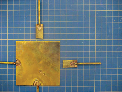
Figure 1. Detail of one of the soldered removable arms and the corresponding notch cut into the back plate (Photography by Hannah Brown) (click image for larger version)
Once the method was devised the first step was to cut an undersized back plate from (recycled) sheet brass (smaller than the outer dimensions of the plaque so as not to be visible when complete) and four short lengths of thin brass rod. To create the two fixed arms, brass rods were soldered into the notches and cut mid-way along two of the edges. On the remaining two sides of the plate a similar notch was cut at the central point of both edges. The two remaining rods for these sides were then each soldered onto a separate small section of brass plate in order to become the moveable arms for the finished mount (Figure 1).
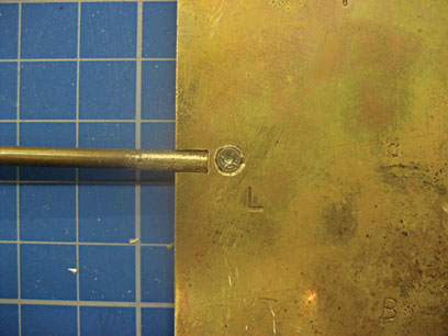
Figure 2. Attaching the removable arm in place to the back plate with an M2 screw (Photography by Hannah Brown) (click image for larger version)
These two units (the back plate and the moveable arm) were then held in place with a clamp, drilled, tapped and countersunk to fit a M2 screw (Figure 2).
It was important that the small section of brass on the end of the moveable arms was located behind the brass plate so the back of the mount remained flush. In order to protect the back of the object from the mount, a section of Plastazote® Foam (closed cell, cross-linked polyethylene foam) was cut to the size of the back plate to form a barrier between the plate and the object (Figure 3).
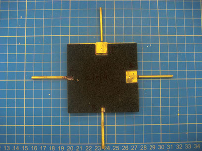
Figure 3. The protective Plastazote layer cut to the shape of the back plate (Photography by Hannah Brown) (click image for larger version)
It was then time to mark out for bending the four arms into place. This was done by laying the mount centrally upon the back of the object so the bending points of the arms could be marked by eye against the edges of the plaque. The mount was then removed from the object and the arms bent with a hammer to create right angles at these points. Once this had been done, the process was repeated to determine where the arms needed to be bent again in order for them to hook around the front of the object (Figure 4). After this process it was necessary to unscrew the removable arms and test the fit of the mount around the object. The arms were then adjusted where necessary before filing, shaping and cleaning the brass. Small sections of conservation grade self-adhesive acrylic tape were then stuck to the ends of the brass arms, where they came into contact with the object, to protect the edges.
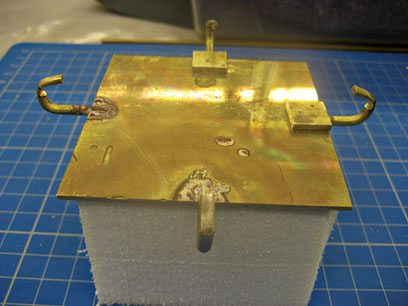
Figure 4. Creating the second bend in the arms to hook around the front of the object (Photography by Hannah Brown) (click image for larger version)
The final process was to cut two 'keyholes' into the brass plate in order for the whole mount to be located onto screws and slid down into place. As before with the removable arms, sections were then cut out of the Plastazote layer to accommodate the screw heads and to prevent the object from getting scratched (Figure 5). As instructed, a fabric-covered slope was made, on which to display the objects at each of the venues.
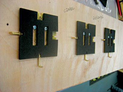
Figure 5. Checking the location of the screws in the ‘keyholes’ cut into the back plate (Photography by Hannah Brown) (click image for larger version)
To achieve a new method of mounting such as this, a great deal of collaboration is required as well as ongoing consultations between each department involved - constantly revisiting the mount design when any necessary modifications need to be made. Although the general method is agreed at the start of the making process, one must be free to change and develop the mount in order to get the most out of the ideas thrown up by the creative process. As it is now incumbent on museums to make greater use of their collections, more and more tours are being agreed and objects loaned than in the past. Conservation and handling issues have meant that the more vulnerable objects have not been able to tour. This has in part been the impetus behind the drive to improve and develop our methods of mount making and packing.
Autumn 2008 Issue 56
- Editorial Comment - Conservation Journal 56
- Displaying stained glass in a museum
- Resources vs access: meeting the challenge
- Costume cleaning conundrums
- Digital Killed the Analogue Star! Care of V&A collection based carrier and machine assisted media
- Observations on the causes of flaking in East Asian lacquer structures
- Practical ethics
- Mount making for the Medieval & Renaissance exhibition tour
- SurveNIR project: non-destructive characterisation of historical paper
- The reconstruction of the materials and techniques of Nicholas Hilliard’s portrait miniatures
- Conservation of a ninth-century bowl from Iraq
- Renaissance painted cassoni
- A forthcoming technical publication of Renaissance frames at the V&A
- Conservation webs
- RCA/V&A Conservation: In-post MA for conservation professionals
- Printer friendly version