Conservation Journal
Autumn 2009 Issue 58 special edition
Sir Paul Pindar's house on the move again
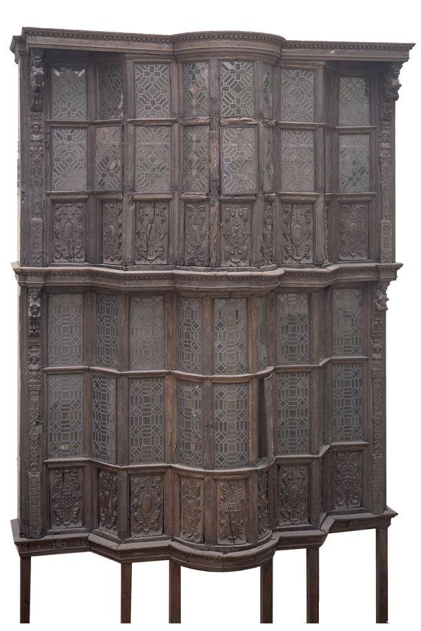
Façade of Sir Paul Pindar's house, Bishopsgate, London 1599-1600 Museum no. 846-1890.
In early 2007, Momart and Taylor Pearce Ltd, art handlers and installers, were appointed to record, dismantle, pack and remove to storage the façade of Sir Paul Pindar's house (846-1890) from its position in Gallery 48 so that it could be re-instated in the Simon Sainsbury Gallery of the V&A's new Medieval & Renaissance Galleries.
The façade was installed in Gallery 48 (the old shop area) in 1909. It comprises of a two-storey, ornate timber façade with a projecting central bay. The overall size is approximately 9.5m high by 5.3m wide by 2.4m deep.
Scaffolding had been erected prior to our involvement to allow for a full survey of the structure to be carried out. CgMs Consulting, planning consultants for archaeology and historic buildings, were commissioned by the V&A to produce measured drawings and identify original and non-original parts of the house façade. These drawings, along with our own on-site drawings and digital photos, were used to form the basis for the recording of the façade during the dismantling.
The floor joists, floorboards and the two side projections are not original, along with the window glass and various parts of the external decorative mouldings. The support structure that fixed the façade to the Museum wall is also non-original timber. Metal ties, fixed between the timbers and rear brick wall were also added in 1909 to provide stability to the façade when it was erected in the Museum.

Figure 1a. Roof boards after removal (Photography by Matthew Nation)
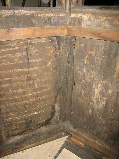
Figure 1b. Fixing method, reverse of panelling (Photography by Matthew Nation)
Basic parameters for the dismantling of the façade were set out by the Museum and were as follows:
- The timber façade was to be dismantled into the minimum number of sections that will allow for transport and packing
- Cutting of original materials was not permitted
- Each section, regardless of size, was to be given a unique reference number and annotated onto drawings
- Each element was to have a label securely attached
- The numerous parts were to be packed for transport and storage
The façade was generally dismantled in the following sequence: the false sides, plasterboard ceilings and wooden boards on top were removed to reveal the 1909 support structure beneath (Figure 1a); the surface mounted, non-structural elements (such as windows, cornice, internal panelling, carved timber panels) revealing the bare bones of the original structure and, finally, the structural elements were carefully dismantled piece by piece. As each piece was removed it was numbered, labelled, measured and its location noted on the drawings. The leaded windows had been mounted into the casements with 6mm square beading pinned into position and also wired onto horizontal metal bars screwed into the mullions. The windows were assessed individually for stability and, if considered necessary, low-tack masking tape was used across vulnerable panels to prevent them dropping out during handling. The tape was removed after the window had been lowered to ground level. The windows were placed in a plywood cradle with Plastazote® cushioning and straps, and lowered to the ground using a Genie lift. Once at ground level, the windows were packed vertically into purpose made plywood cases.
The carved timber panels beneath each window had been fixed into location on the historic framework using bent over nails as clamps (Figure 1b). These needed to be carefully extracted, bent or cut to release the panels.
With both the windows and carved panels removed, along with all other non-structural coverings such as architraves, the main structure could be dismantled. In order to maintain stability during the dismantling process, temporary supports were needed on some of the structure; this was achieved by using the scaffold and bracing the timber between poles with Plastazote softening. Scaffolders were on-call throughout the dismantling to adapt the scaffolding as required.
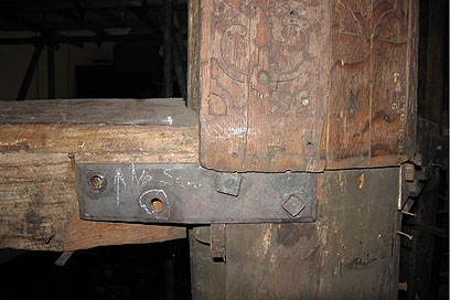
Figure 2a. Joints and fixings (Photography by Matthew Nation)
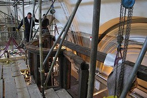
Figure 2b. Bressummer beam removal (Photography by Matthew Nation)
The original mortice and tenon joints on the large structural timbers were still intact and most of them fitted together as they would have originally. New timber pegs had been employed in 1909 to secure the original mortice and tenon joints and, in addition, there were numerous screws, nails and surface-mounted metal brackets used to strengthen the joints (Figure 2a). The large timbers were lifted using block and tackles whilst the smaller elements were light enough to be lifted manually. Timbers were lowered to ground floor with an electric hoist, either by slinging the piece directly or placing smaller parts onto a pallet base. Working from the top down i.e. starting with the second floor, the framework was removed in the following sequence:
The metal ties were removed to free the structure from the gallery wall. The long bressummer beam, spanning the entire width at the rear of the frame was released by removing wooden pegs and all other fixings at the joints. It could then be lifted clear and lowered to ground level (Figure 2b). The outer vertical timbers could then be freed, and by carefully tilting them away from the framework at the top, the short horizontal elements could be carefully removed (Figure 3a). With this framework removed from either side, it left the central, three-windowed semicircular bay standing on its own, enabling this very large part of the structure to be removed as a complete unit due to it still retaining the original joints that had not been previously disturbed. In order to minimise any movement between the original timbers and to provide a structure for lifting the bay, a timber framework was constructed around the entire bay. This was then lifted clear and lowered to ground level (Figure 3b).
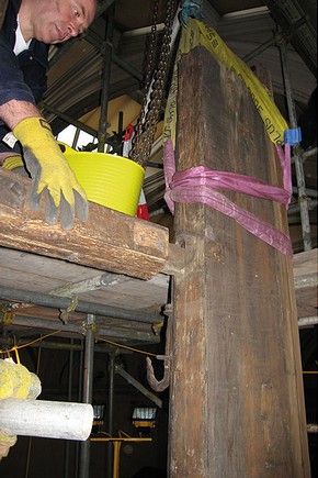
Figure 3a. Vertical timber being removed (Photography by Matthew Nation)
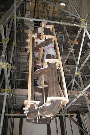
Figure 3b. Bay being lowered (Photography by Matthew Nation)
With the second floor removed, the first floor could then be dismantled in the same manner until the whole façade had been removed from the Museum wall. The façade is re-constructed in a slightly different manner to the 1909 installation. The aim being to remove as much non-original material from the façade as possible. Contemporary steelwork was designed to give structural support but with as little interference of the original timbers as possible. The house front is suspended from a wall and 'hangs in space', giving a much greater sense of a fragmentary façade, and providing an exciting display of this magnificent timber structure.
Autumn 2009 Issue 58 special edition
- Director's acknowledgement
- Editorial comment - Conservation Journal 58
- Designs on the future: Developing the new Medieval & Renaissance Galleries
- Aspects of the role of Lead Conservator
- Behind the scenes: Conservation and audience engagement
- Medieval & Renaissance Galleries: A passive approach to humidity control
- What's the difference? Climate comparisons for the Medieval & Renaissance Galleries
- A method statement for the Medieval & Renaissance Galleries
- Medieval & Renaissance Galleries conservation progress logs
- New mounts for the headless stone boy and his brother
- Sir Paul Pindar's house on the move again
- Loss compensation at the first floor interior panelling: Sir Paul Pindar's house front
- Training through collaboration - conservation of the Camaldolese Gradual
- A stucco relief by Francesco di Giorgio Martini: Conservation and technical considerations
- The Bourdichon Nativity: A masterpiece of light and colour
- Deteriorated enamelled objects: Past and present treatments
- Stained and painted glass from the Chapel of the Holy Blood, Bruges
- 'This burden of light is the work of virtue': Research on the Gloucester Candlestick
- Digital in-fills for a carpet
- Master Bertram's Apocalypse Triptych: To clean or not to clean
- Professional development in a project culture
- Work in progress: Holbein's drawing processes
- Conservation: Principles, Dilemmas, and Uncomfortable Truths - a summary
- Acknowledgements and Conservation Department staff photograph
- Conservation Department staff chart
- Editorial Board & Disclaimer
- Printer Friendly Version
- Work in progress: the development of the Medieval & Renaissance Galleries